
STBY ELEC PWR INOP light during preflight
-
@RealPax
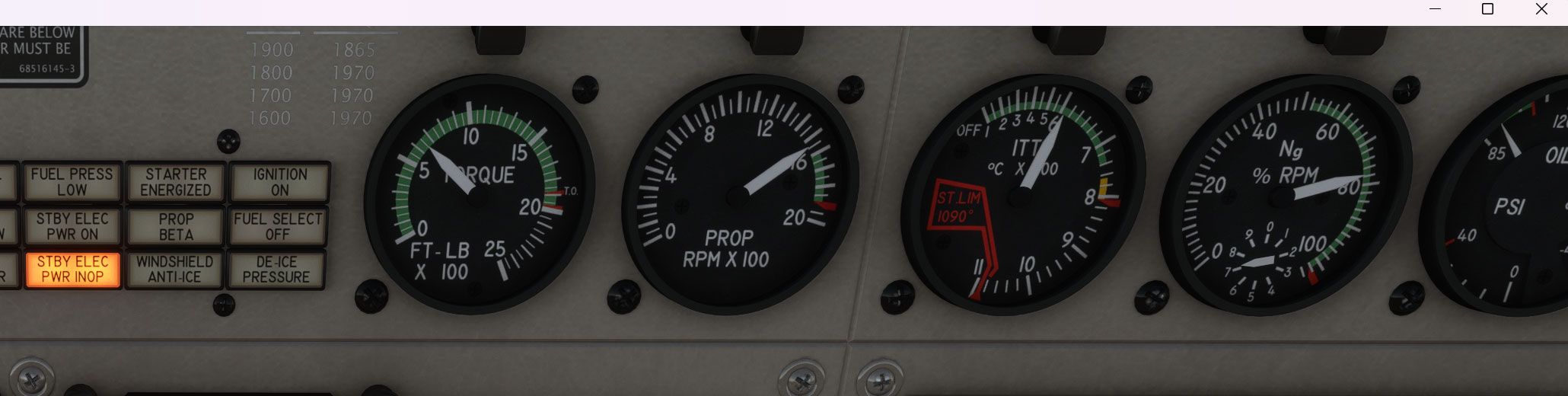
Same test flight,Wider view.
I was thinking the same thing about "manually delete the files from the community folder and reinstall" Just wanted to see if I was missing something else?
-
Turn the knob on the amm/voltmeter on the left side to the Gen and Alt positions and show screenshots. I mixed up the above screenshots and didn't realize one was saying PWR ON, I thought it was OFF and INOP, so unless the generator is failed, which I doubt given that you've been looking at the failure screen, I'm curious what the generator and alternator power draws are.
@jmarkows hey, I'm not OP but having the same issue so I'll pick up where he left off.
I just have a picture with the amm/voltmeter switch in the Gen position, but switching to Alt does not cause the needle to move at all. Both show the same reading. Also, moving the Gen switch to Reset and Trip have no effect on the amm/voltmeter.

-
I have a similar in that mine STBY ELEC PWR on will not clear no matter what I do. I do the comple run up check list. If I turn off the standby alt power, I get the "STBY ELEC PWR INOP" warning light. What has me wondering is that I start my flight in MSFS 2024 on the runway rather than a cold start. Is that what is causing the issue?
@pyarb15 My guess would be the generator is not running. If I got you correct you start on the runway. If the "STBY ELEC PWR INOP" is on this would indicate the generator is not running or does not produce sufficient power for all your aktiv systems.
First step would be to push the Generator Button to "Reset" once. This should aktivate the generator. Make sure your power lever is at least at idle better above (try 70% power just to be sure). And your mixture is at "High Idle". This should give you enough power from the generator.
Check also your failure page on the panel, maybe there is a generator failure. -
@pyarb15 My guess would be the generator is not running. If I got you correct you start on the runway. If the "STBY ELEC PWR INOP" is on this would indicate the generator is not running or does not produce sufficient power for all your aktiv systems.
First step would be to push the Generator Button to "Reset" once. This should aktivate the generator. Make sure your power lever is at least at idle better above (try 70% power just to be sure). And your mixture is at "High Idle". This should give you enough power from the generator.
Check also your failure page on the panel, maybe there is a generator failure.@RealPax, no, actually, it shows STBY ELEC PWR ON was saying if I flip the the stby elec pwr to off, then it shows STBY ELEC PWR INOP, which I think would be expected. My issue is that the STBY ELEC PWR ON will not clear even after going through the run-up checklist, which includes the reset (I am also outside the beta range while doing so). No failures indicated, and even went as far as resetting the engine health.
-
I just reviewed the code to see what I could find here. I've only seen a handful of reports about this, while it seems to be working for most users. My immediate thought was the usual hardware bindings. After my code review, I'm sill inclined to believe that is where the issue lies.
The light will illuminate only when...
- The standby alternator bus is connected to the main bus (will happen when the switch is thrown)
- The main bus is at at least 16V (should always be the case during normal operation)
- When the alternator is energized.
This last point is likely where the issue is. This can happen in two ways...
- When hardware/software is sending the associated alternator event to activate the alternator.
- When correctly set by the code in the aircraft, when...
a. The main generator is off.
b. The main generator is on, but the battery is discharging at more than 5A.
If you cannot find any type of hardware or software input that might be affecting any of the conditions listed above, then the best thing to do would be to sent me screenshots of everything you can think of. This would include the tablet's live schematic, the multi-meter, the whole panel with all the annunciators and engine instruments, and if anyone is ambitious, perhaps some of the underlying variables discussed above, if you're familiar with reading them in 3rd party applications. Thanks for any help!
@Black-Square Thank you for the response. Here are some more photos showing different switch configurations and their Ammeter readings. All photos taken while in cruise. I do use a couple peripherals but i double-checked my bindings and i have nothing bound related to the alternator, generator, or anything electrical, except lights.
Let me know if i can get you any more info.


-
@Black-Square Thank you for the response. Here are some more photos showing different switch configurations and their Ammeter readings. All photos taken while in cruise. I do use a couple peripherals but i double-checked my bindings and i have nothing bound related to the alternator, generator, or anything electrical, except lights.
Let me know if i can get you any more info.
Wow, those photos uploaded really blurry. Here is a link to where they are hosted for full quality. link text
-
@Black-Square Thank you for the response. Here are some more photos showing different switch configurations and their Ammeter readings. All photos taken while in cruise. I do use a couple peripherals but i double-checked my bindings and i have nothing bound related to the alternator, generator, or anything electrical, except lights.
Let me know if i can get you any more info.
@V1RotateAP Thanks for the screenshots. That's exactly what I was looking for. Here is what I have been able to determine from my testing:
-
The standby alternator is energized, and contributing power to the aircraft.
-
The two annunciator lights are behaving correctly, as all conditions appear to be met.
-
Indications on the tablet are confused, because my variable
L:var_AlternatorOnlineis not true. We can see this with the red line through the ammeter (reading zero), which both rely on this variable.
There are two avenues we could pursue from here:
-
Why is
L:var_AlternatorOnlinenot being set correctly, despite all conditions appearing to be met. -
Why is the alternator energized to begin with.
I'm inclined to investigate the first point, since, technically,
L:var_AlternatorOnlineshould have no impact other than the visuals displayed on the tablet, while the electrical system is causing the annunciators to illuminate, and causing unexpected electrical behavior.Again, here is where I would suspect a hardware issue (even though I emulated this in my testing, and it caused
L:var_AlternatorOnlineto be set correctly.To further test this, I would recommend temporarily binding a key combo to
Toggle Alternator 2in the simulator's controls menu. Then, try toggling the alternator manually and see what happens. Either, it will...-
Toggle back on by itself.
-
Remain toggled off.
If #1, then it's more likely a code-side problem.
If #2, then it's more likely a user-side problem.
I really appreciate the help, and the testing above would provide exactly the kind of information I need next. Thank you so much!
-
-
@V1RotateAP We are hoping to release the Caravan v1.2 update and send it to the Marketplace early this week before I travel to record sounds for the Twin Commanders. I hate to nag a volunteer, but if you had a chance to run this test over the weekend, I would super appreciate it
")
-
@V1RotateAP We are hoping to release the Caravan v1.2 update and send it to the Marketplace early this week before I travel to record sounds for the Twin Commanders. I hate to nag a volunteer, but if you had a chance to run this test over the weekend, I would super appreciate it
@Black-Square said in STBY ELEC PWR INOP light during preflight:
before I travel to record sounds for the Twin Commanders.
Nick, have you ever considered writing about your experiences developing your aircraft? I enjoy seeing how things are made like this, and I had always figured that sounds were as "simple" as calling Boris and saying "Hey, I need Turbo Commander sounds. Next month? Sounds good, thanks."
Do you ever get to fly any of the planes you model over the course of going out and studying them?
-
@V1RotateAP We are hoping to release the Caravan v1.2 update and send it to the Marketplace early this week before I travel to record sounds for the Twin Commanders. I hate to nag a volunteer, but if you had a chance to run this test over the weekend, I would super appreciate it
@Black-Square
First, let me say I'm super sorry. I feel like an absolute dope. I wasted your time.
I dug deeper and found a binding for ALT ON that I was unaware of. I removed that. Now everything works perfectly as it should. Thank you for the help and the fantastic airplanes you make! -
@Black-Square
First, let me say I'm super sorry. I feel like an absolute dope. I wasted your time.
I dug deeper and found a binding for ALT ON that I was unaware of. I removed that. Now everything works perfectly as it should. Thank you for the help and the fantastic airplanes you make!@V1RotateAP On the contrary, you have made my day by confirming that this is a hardware issue
Thanks for letting me know. -
@V1RotateAP We are hoping to release the Caravan v1.2 update and send it to the Marketplace early this week before I travel to record sounds for the Twin Commanders. I hate to nag a volunteer, but if you had a chance to run this test over the weekend, I would super appreciate it
@Black-Square said in STBY ELEC PWR INOP light during preflight:
"...before I travel to record sounds for the Twin Commanders."

-
R RealPax referenced this topic on