
Down the Rabbit Hole with VLF / Omega
-
Starting this thread because I have a series of increasingly down-in-the-weeds thoughts and questions regarding VLF/OMEGA. I'm fascinated by these navigation systems. I used to have a pretty good handle on the theory, and I still hold an FCC General (formerly First Class) Radiotelephone Operator's License, though I've not used it professionally in years.
So, first question: If one is flying without GPS or GNSS, and there's been enough drift for the Update VLF message to appear, and I don't correct it, will I always arrive spot-on target, or could I end up anywhere within the calculated uncertainty radius?
-
I fly without using the GNSS, though I can't say I've needed to update other than my initial position on the ground.
Do you have DME/DME updates disabled? If so, as long as you're in range of some known DMEs, you're fine.
If you don't or otherwise have it disabled, given Nick's dedication to his literal and figurative craft, I would imagine it works as you think it will. There is some amount of dead reckoning going on, as well, which might mitigate it for a while.
-
My understanding is that VLF during the Starship age was pretty efficient at keeping things in phase and calculated correctly, regardless of propagation. As hams, we tend to think of HF being poor at lower frequencies during the day and better at night, and accounting for atmospheric/solar conditions. VLF was used in the same way as VOR or NDB, they just traveled much farther. You would be able to tune them in being airborne rather well in most cases, but had to augment their use with VOR and NDB or better navigation accuracy. So the VLF alone would get you to a "sector" just fine, but to locate an actual airport or more precise location, you had to rely on VORs and NDBs. They were old systems as well. Ships and submarines likely had to rely on other technologies and methods to be accurate. VLF alone in a plane would only be so good and at some point you'd have to rely on ground-based visuals to find certain places. We forget that in the oldest age of aviation, navigation was visual and light-based. Here is a very well made video on the Air Mail Routes: link text
-
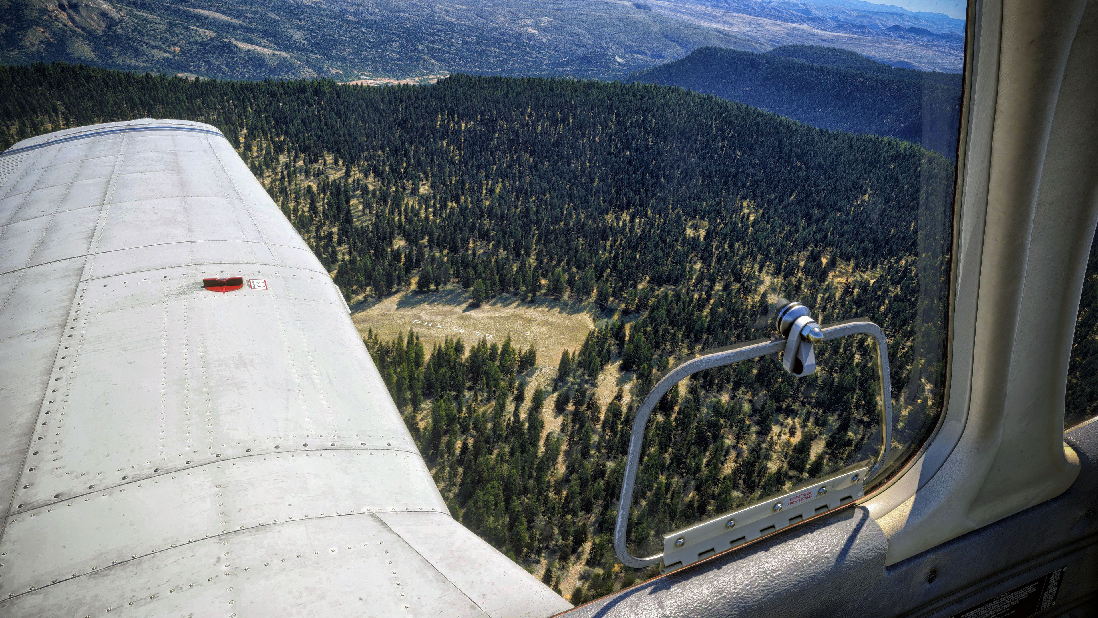
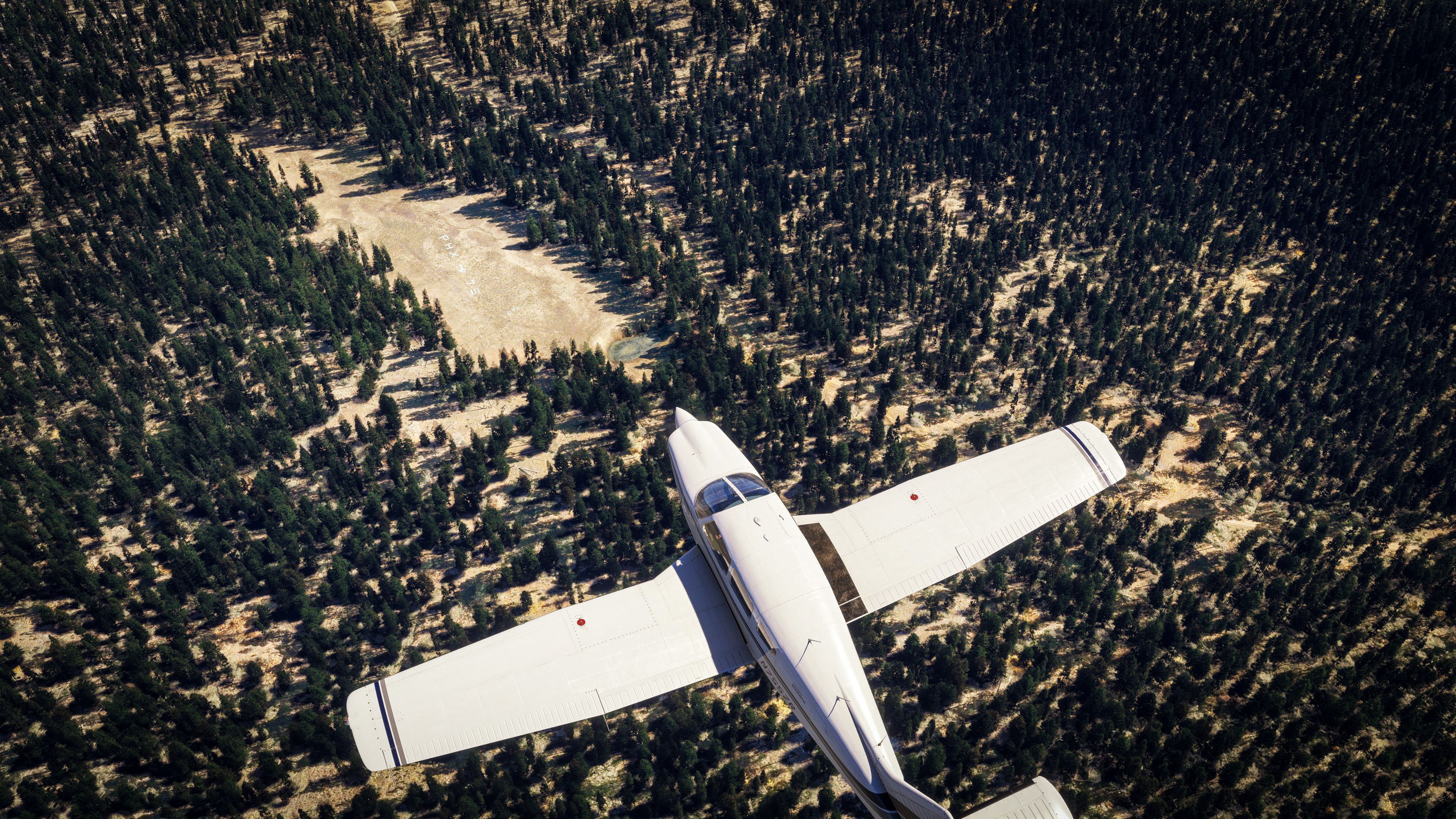
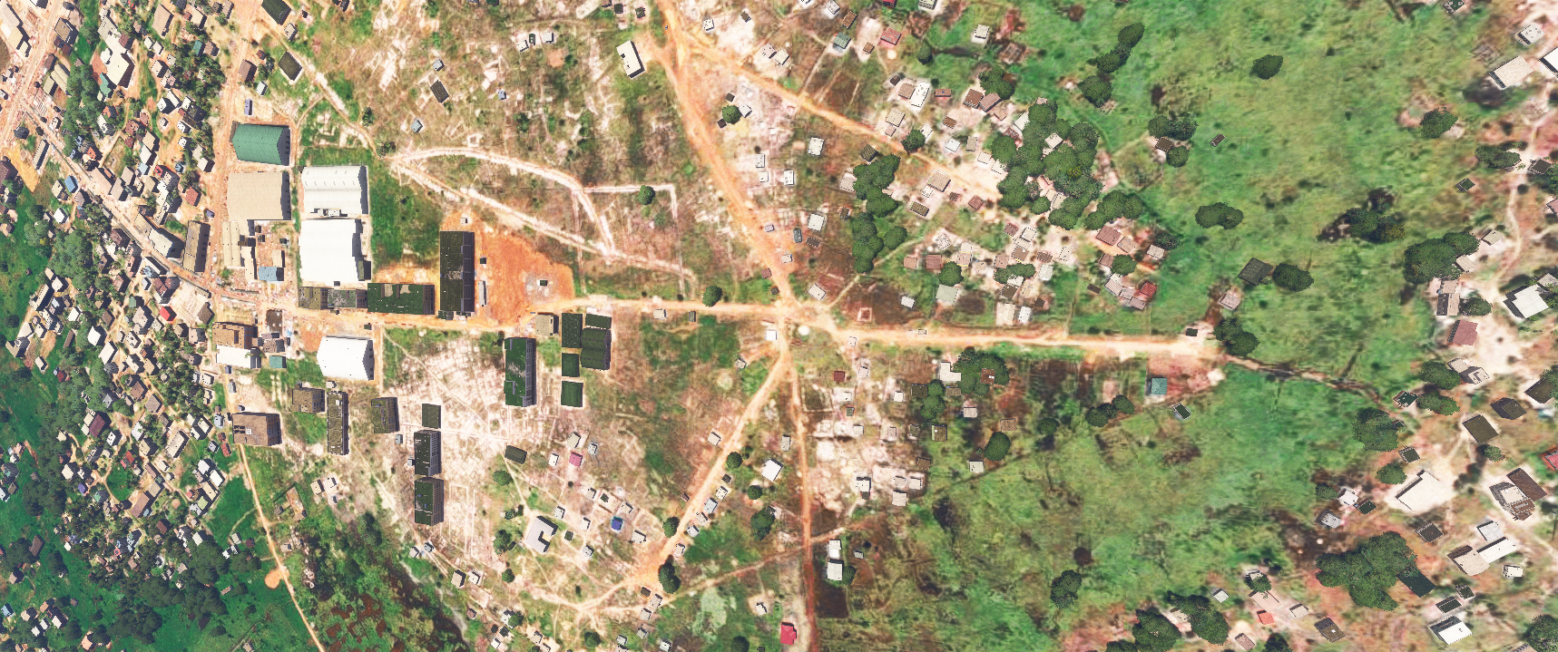
I wanted to see if a certain air mail route visual point was visible in the sim. Not only was it visible, it was as if someone added the texture to enhance it's visibility! Crazy how amazing the sim can look at certain locations. This is in the woods near Pine Az, a rather remote location. Hand-Crafted Air Mail Reference site
-
I made a set of VLF/Omega station userpoints for Little Navmap:
https://flightsim.to/file/97460/vlf-omega-userpoints-for-little-navmap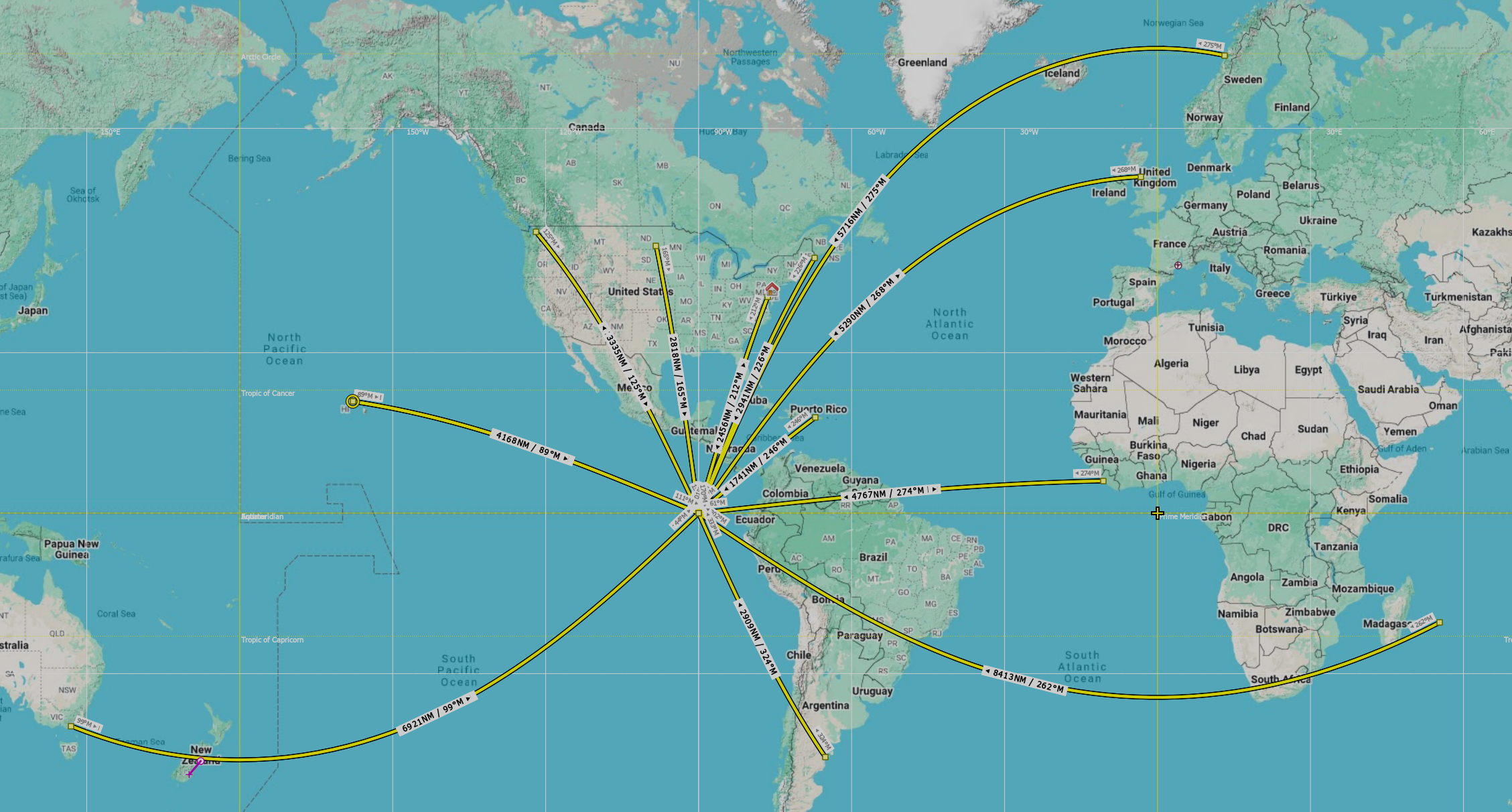
-
Recently I've been spending a lot of time with the CDU and MFD JavaScript code trying to get a handle on what's going on under the hood (spoiler: it's a LOT!).
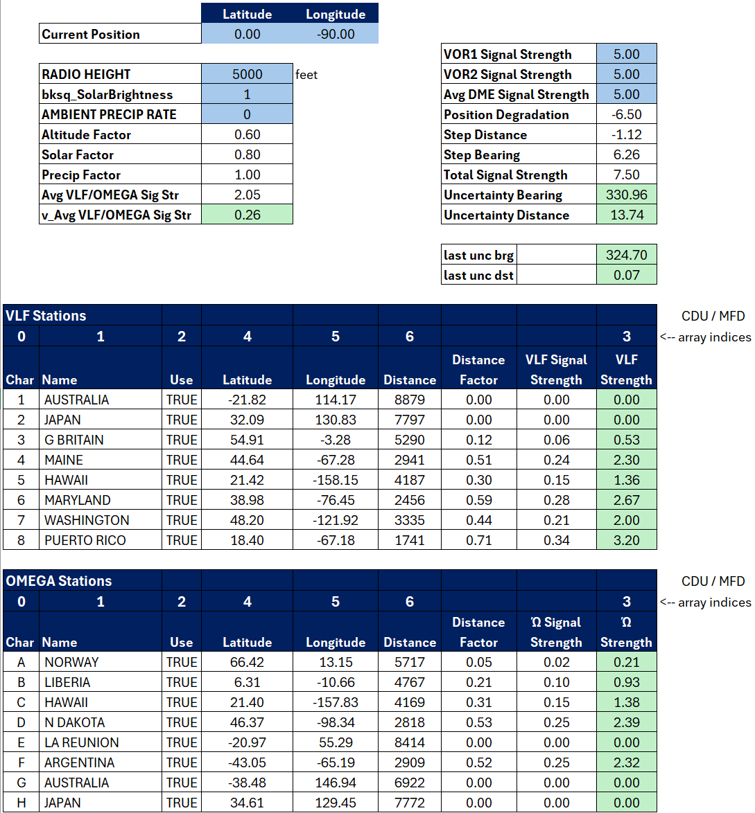
I have been able to reverse-engineer most of the "updateVlfOmega" and "updatePositionUncertainty" routines, and port their calculations into Excel. I'm pretty confident with the updateVlfOmega calculations, but there are some outstanding questions on PositionUncertainty. I can plug in a set of coordinates in Excel and it will show the signal strength results as well as intermediate calculations such as great circle distance between the station and aircraft. You can adjust the radio height as well as atmospheric factors to see how they affect the results. If there were a SimConnect plugin for Excel, the workbook could even be dynamic, generating results in real time as the aircraft moves.
Just for kicks, I took the VLF/OMEGA station userpoints I created for Little Navmap and created a "flight plan" (see prior post) showing the distances from each station to a common point (I picked coords 0,-90 just off of the Galapagos islands). The great circle distances shown on Little Navmap are pretty close to the calculated values in Excel.
-
Awesome thread! I was happy to just "let it be" but I'm now even happier knowing more, fascinating stuff!
-
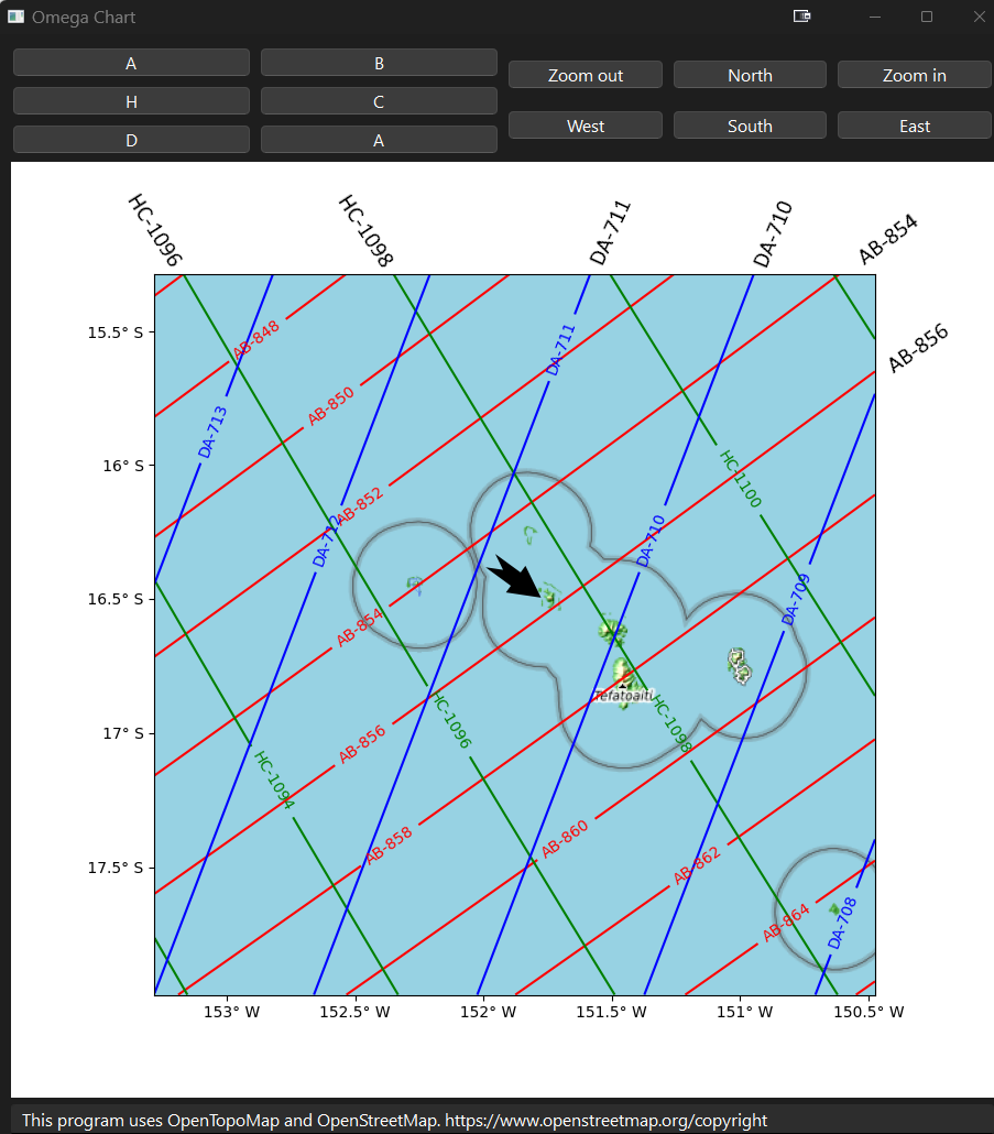
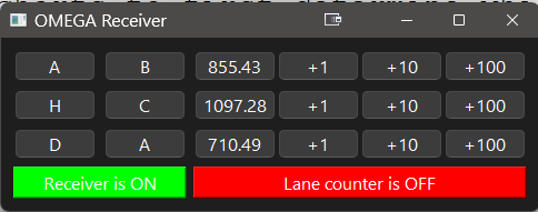
Early Omega systems required the navigator to manually plot their position using specially prepared charts. The navigator would use these charts to first determine which pairs of Omega stations to use, two or three pairs. Each pair would establish a series of "lanes", similar to latitude/longitude but based on the signal propogation between the two stations. Given at least two pairs whose paths criss-cross (not all paths cross in all areas of the world), the aircraft's current position would be entered into the Omega receiver as a "lane counter" value for each station pair. Once airborne, the lane counters would increment/decrement as the aircraft progressed, and the navigator would read the lane counter values from the receiver and plot the new position using the special Omega charts.
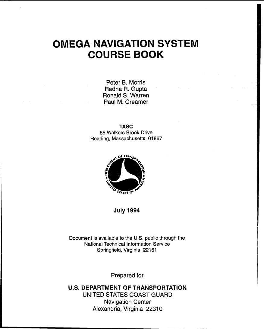
There's a 3rd party freeware Omega simulator for MSFS that emulates the manual plotting form of early Omega navigation, with a receiver displaying station pairs and lane counters, and corresponding charts. It's an external app, and works with both 2020 and 2024. The documentation includes a scan of an original US Coast Guard "Omega Navigation System Course Book". If you want a super-deep dive into radio wave propogation, this is for you. In later systems like the Starship, the nav computer did the math and all the nitty-gritty was hidden from the end user.
https://flightsim.to/file/74110/omega-navigation-system
Here's an example of using the app to set our position at Bora Bora (I picked Bora Bora because it's easier to see the lanes on the chart). Bora Bora is indicated by the black arrow. I chose station pairs A-B, D-A, and H-C. Each lane counter in the receiver is set to the nearest bounding lane.
-
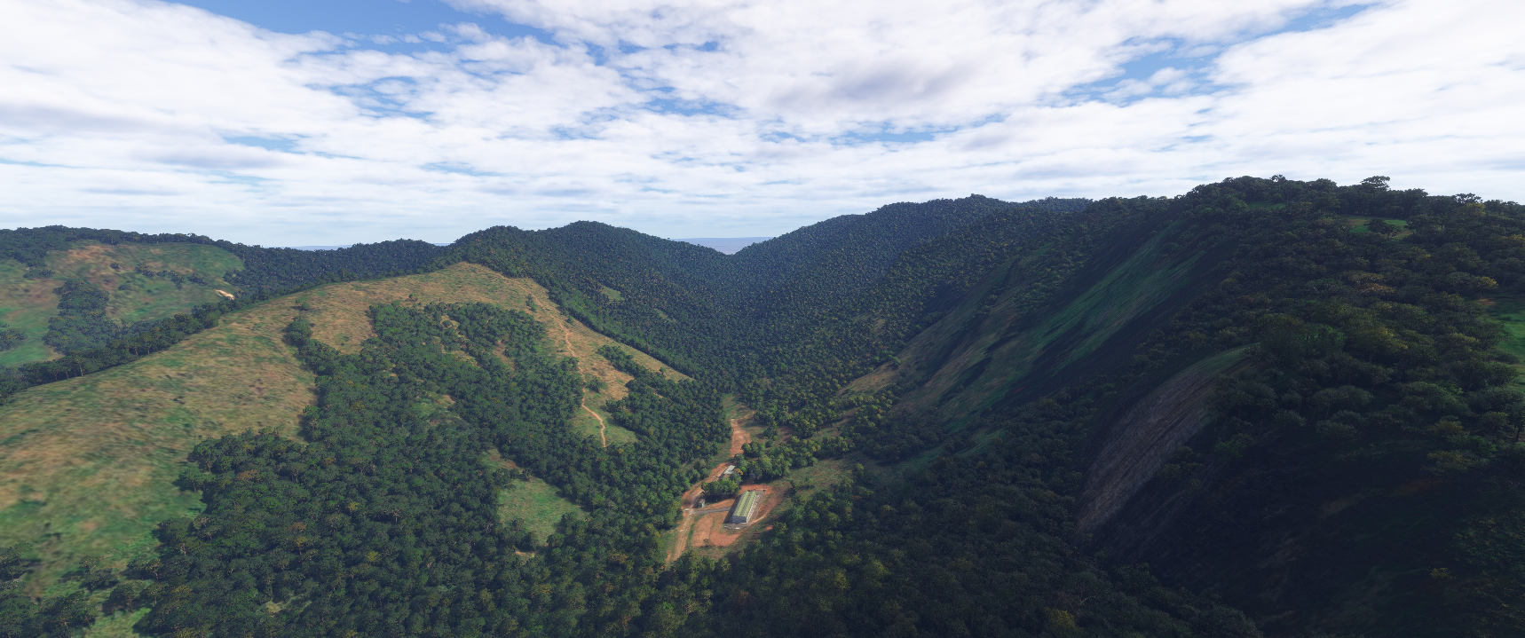
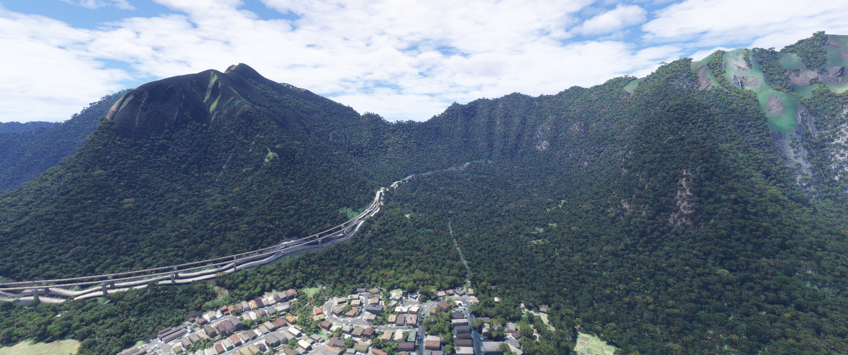
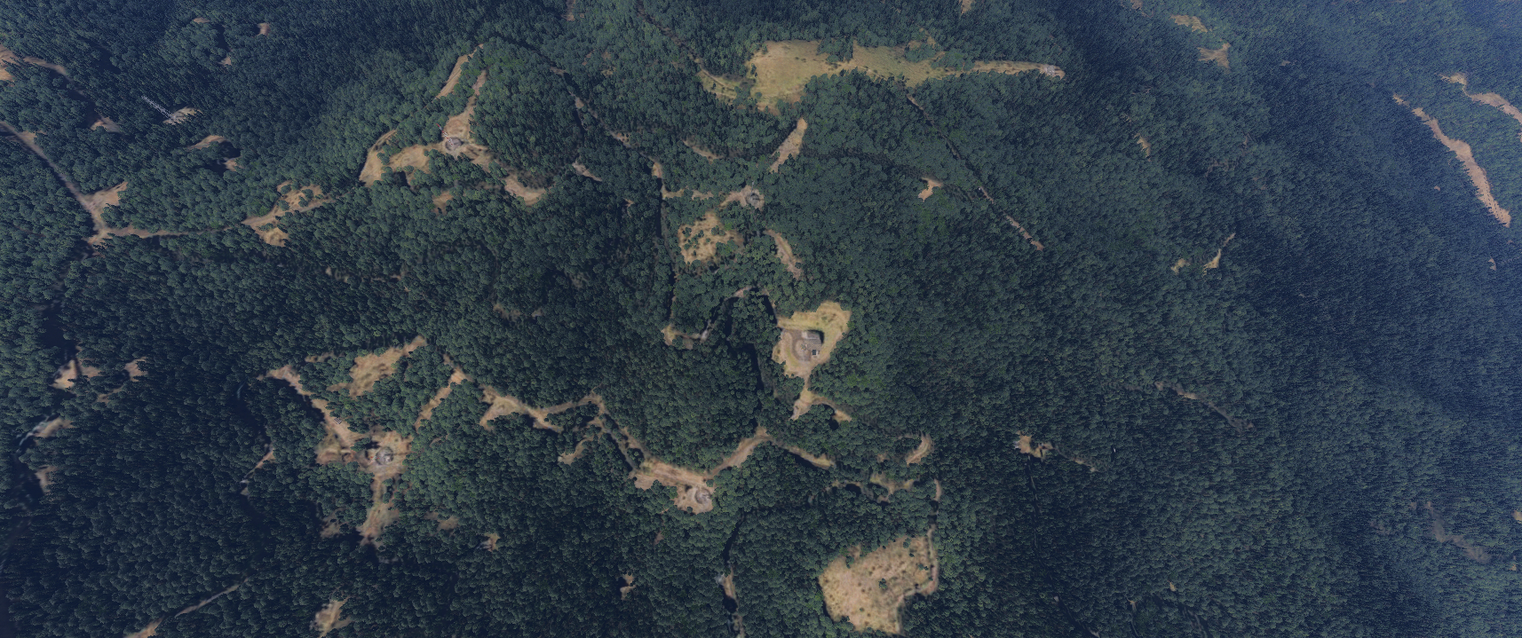
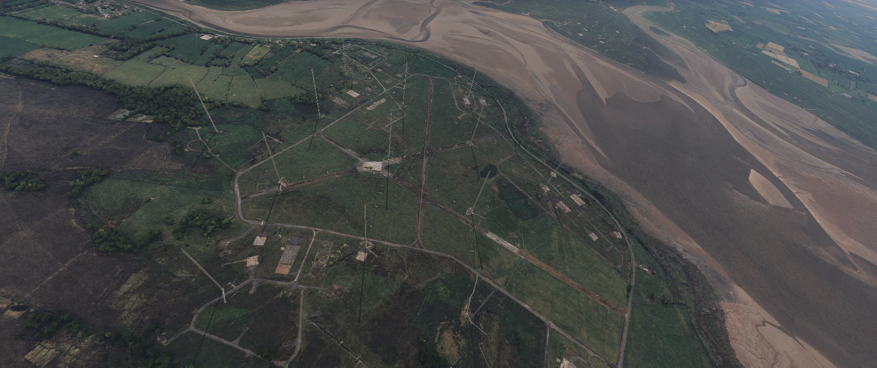
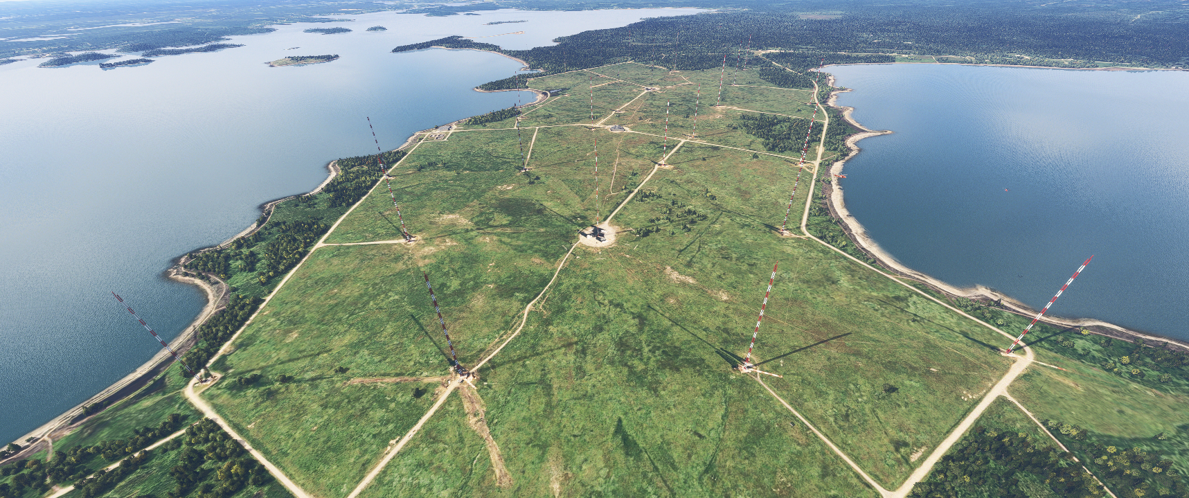
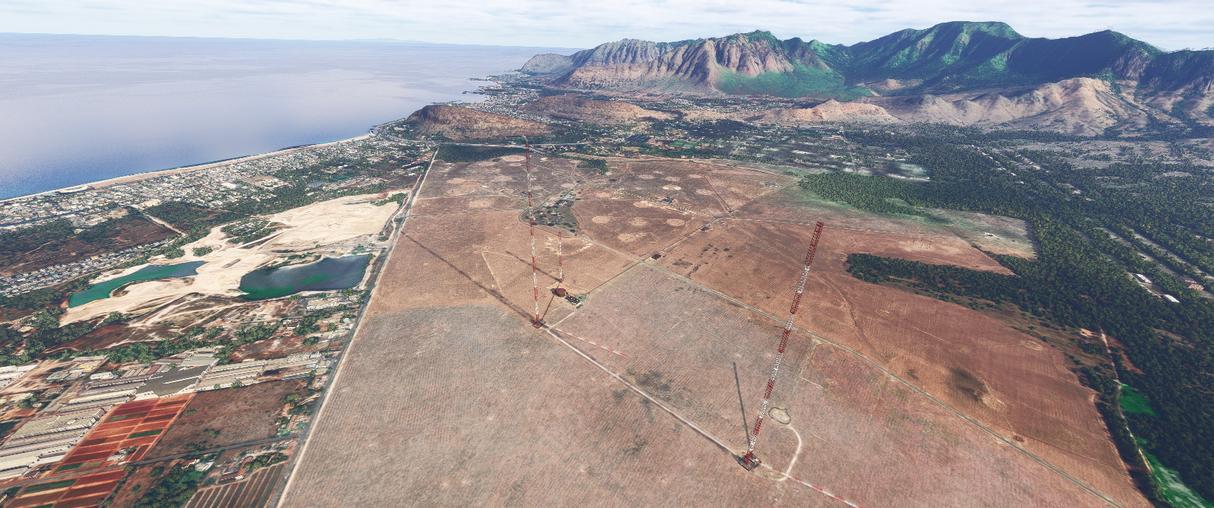
FIELD TRIP!
I went to each of the Omega and VLF sites in the sim to see how they looked. There's not much left of the Omega stations, but most of the VLF sites appear to still be in use.
OMEGA STATIONS
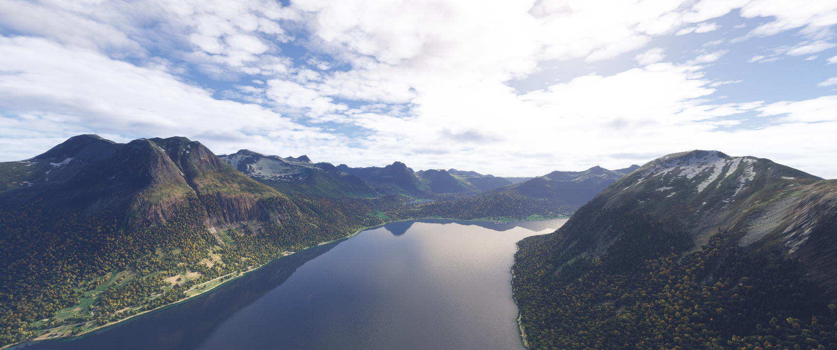
Omega Station A, Norway
The Bratland Omega transmitter, Station A, was the only European transmitter. It consisted of several wires strung over the fjord between the mainland (left) and the island of Aldra. It was dismantled in 2002.
Omega Station B (pre-1976), Trinidad
The Trinidad Omega transmitter was the original Station B until 1976, when the station was relocated to Liberia. In 1988, the building housing the transmitters was destroyed in a fire and subsequent explosion which resulted in multiple casualties and fatalities.
Omega Station B (post-1976), Liberia
The Paynesville Omega transmitter for Station B was put into service in 1976, replacing the Trinidad station. It featured an umbrella antenna mounted on a 417 metre mast, and was the tallest structure in Africa. The station was decommissioned in 1997 and the mast was demolished in 2011.
Omega Station C, Hawaii
The Kaneohe Omega transmitter, Station C, was located on the windward side of Oahu island. It was one of two US Coast Guard stations. Its antenna was a wire spanning the Haiku valley.
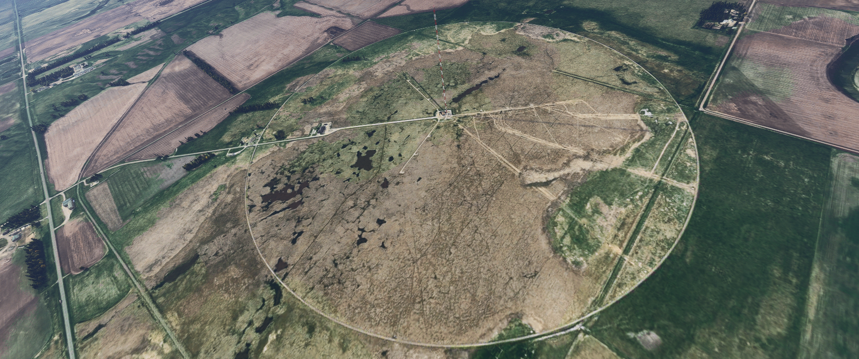
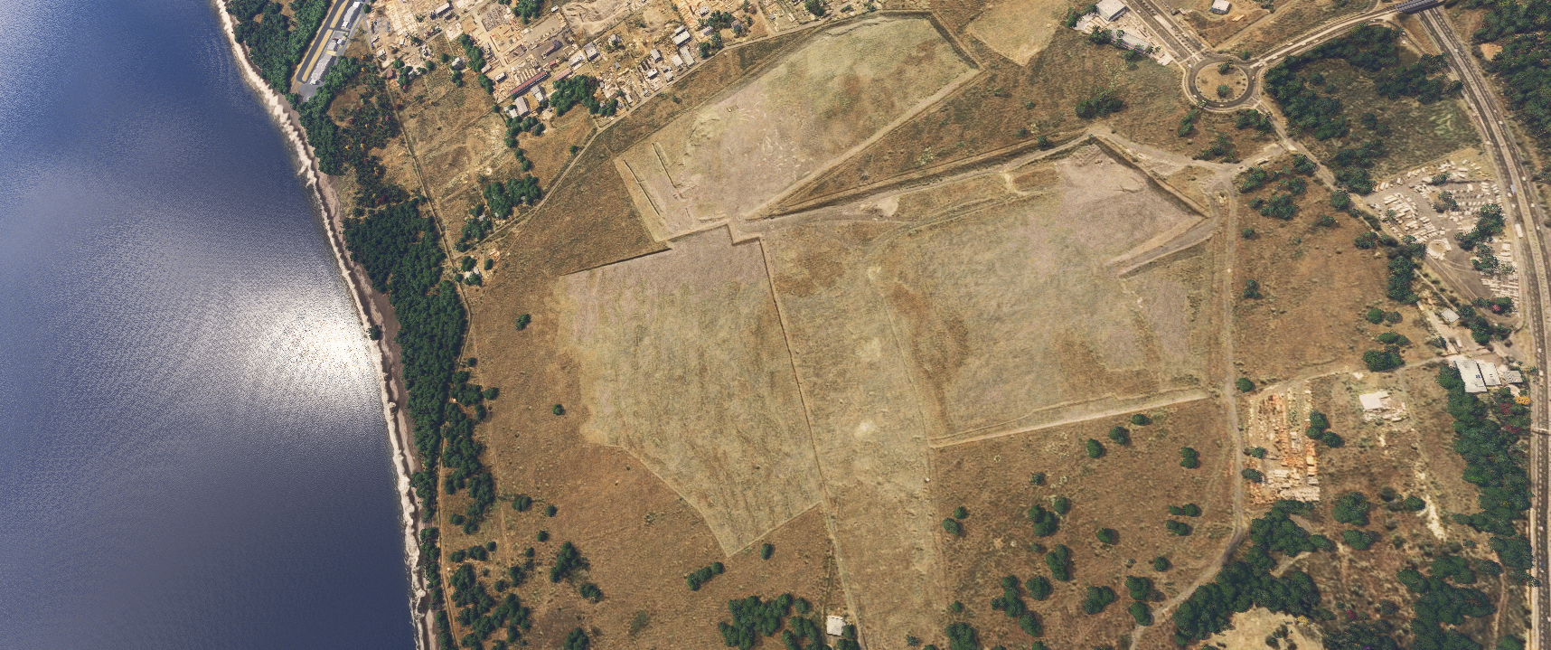
Omega Station D, North Dakota
The La Moure Omega transmitter, Station D, was the other Coast Guard station. It used a 365 metre guyed mast as its antenna. After Omega, it continued in service as a VLF submarine communications station.
-
OMEGA STATIONS (continued)
Omega Station E, Reunion Island
The Charbrier Omega transmitter, Station E, was stationed on the northwest coast of Reunion Island. It used a 428 metre guyed mast, which was demolished in 1999.
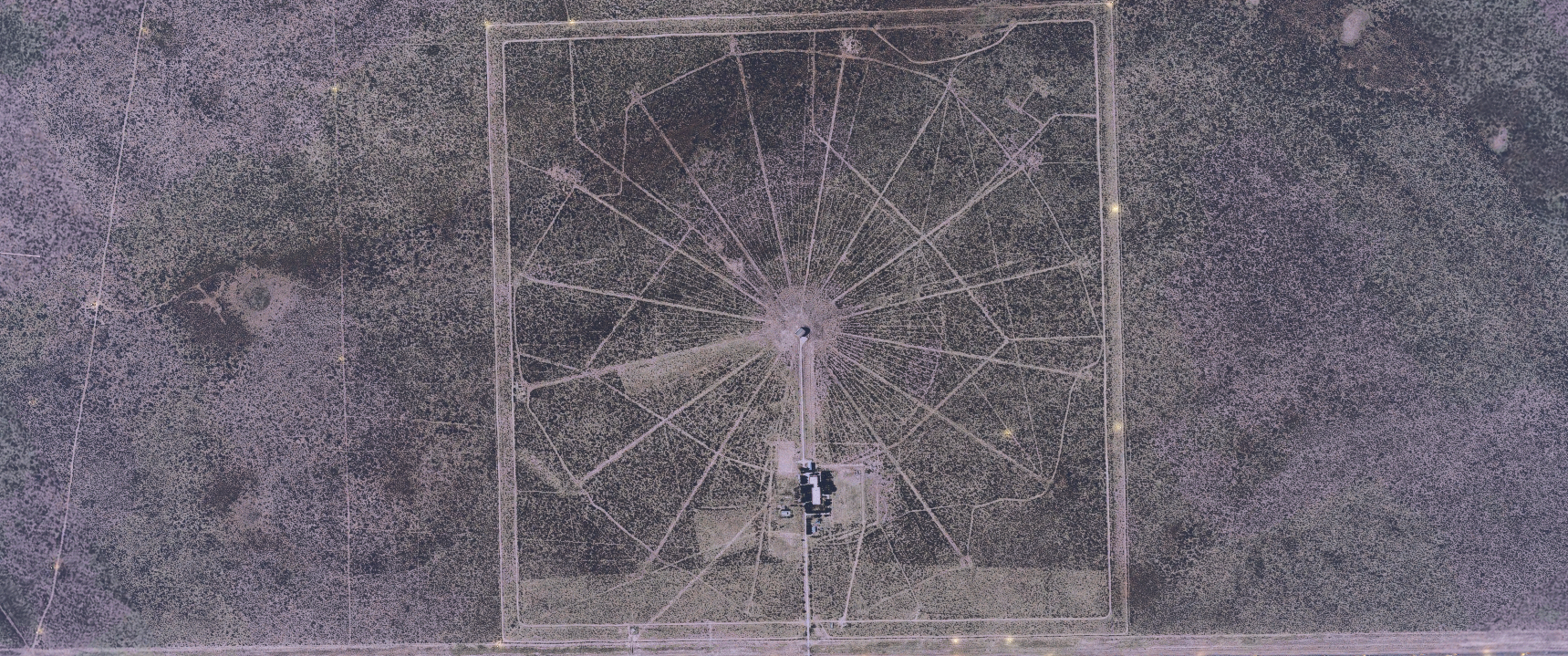
Omega Station F, Argentina
The Trelew Omega transmitter, Station F, was a 366 metre guyed mast antenna, at the time the tallest structure in South America. It was imploded in 1998.
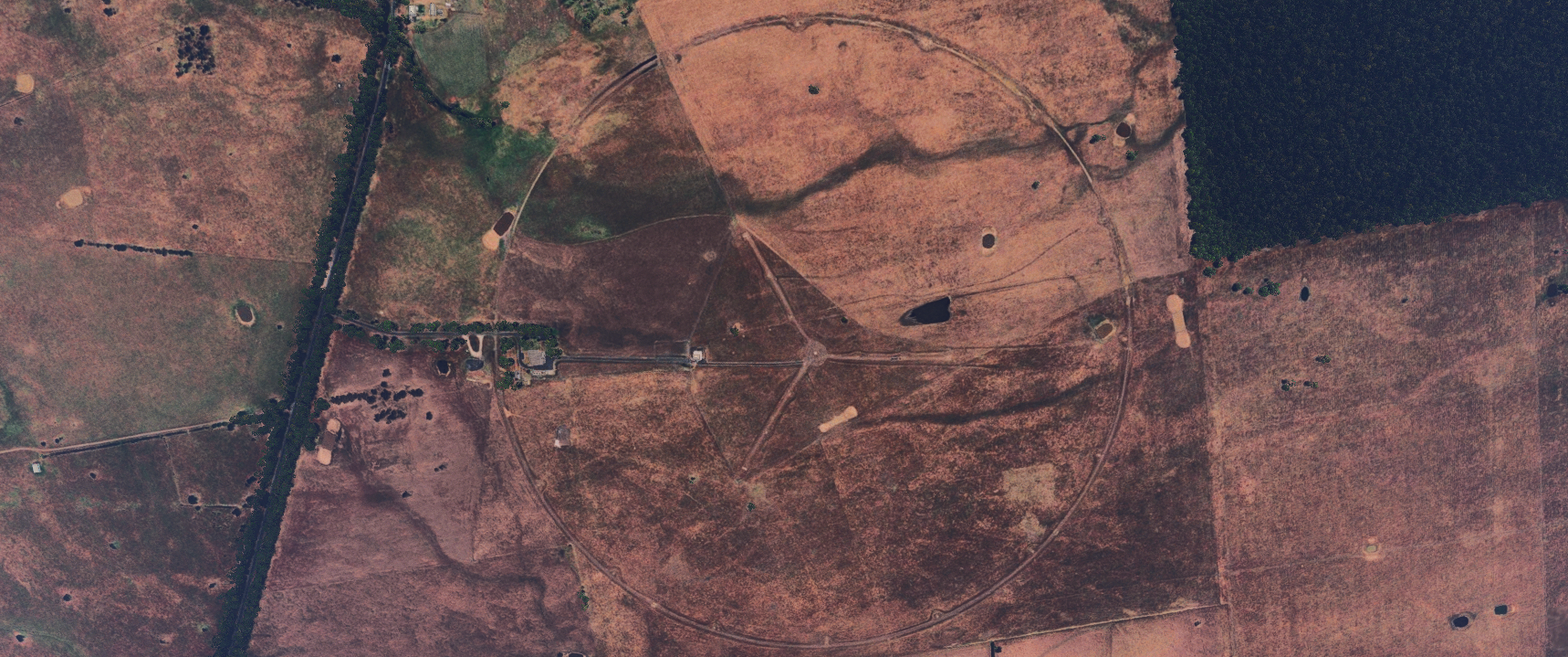
Omega Station G, Australia
The Woodside Omega transmitter, Station G, used an umbrella antenna on a 432 metre guyed mast. It was completed in 1982. After Omega, it served as a submarine communications station until 2008, and was finally demolished in 2015.
Omega Station H, Japan
The Shushi-Wan Omega transmitter, Station H, used a 389 meter tubular steel mast. It was built in 1973 and was the tallest structure in Japan. It was dismantled in 1998.

-
VLF STATIONS
Many of the VLF stations are still in service, used by various militaries for naval communications to ships and submarines.
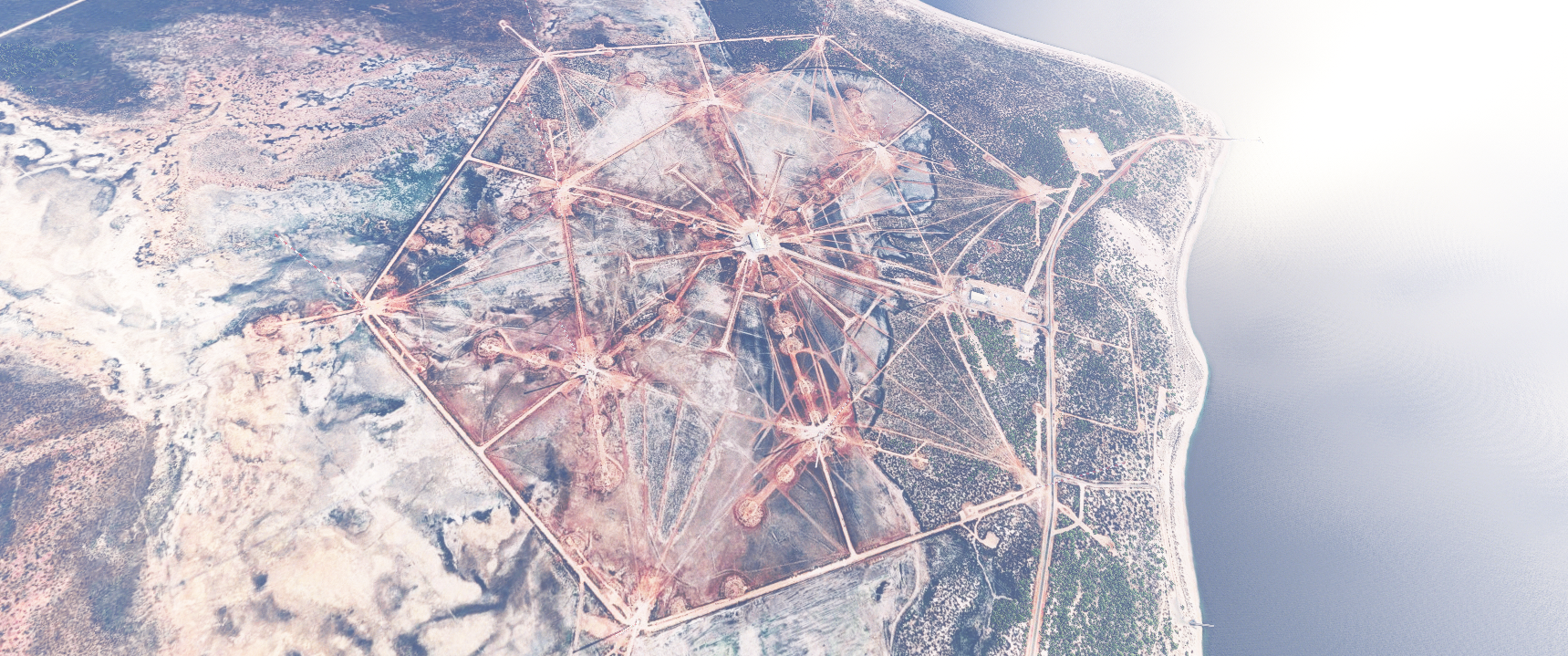
VLF Station 1, Australia
Station 1 is Naval Communication Station Harold E. Holt, located on the northwest coast of Australia. The antenna farm features 13 towers, the tallest of which is 387 metres tall and for many years was the tallest structure in the Southern Hemisphere. Today, the station provides VLF communications to US and Australian ships and submarines in the Pacific and Indian oceans.
 ![VLF 2 Japan.png]
VLF Station 2, Japan
Station 2 is operated by the Japan Maritime Self-Defense Force. It was completed in 1991. The antennas are arranged in two rows of four towers each, ranging from 160 to 270 metres.
VLF Station 3, Great Britain
Station 3 is located in Anthorn, Cumbria. It consists of a 228 metre central mast and twelve supporting masts in a six-pointed star arrangement when viewed from above.
VLF Station 4, Maine
Station 4 is operated by the United States Navy at Cutler, Maine. The antenna system is extensive, consisting of two identical umbrella antenna arrays with a tall (304 metre) central mast surrounded by twelve supporting masts.
-
VLF STATIONS (continued)
VLF Station 5, Hawaii
Station 5 is located on the leeward side of Oahu island in Hawaii, opposite the defunct Omega Station C. It was built in 1972 and features two guyed masts 458 metres in height.
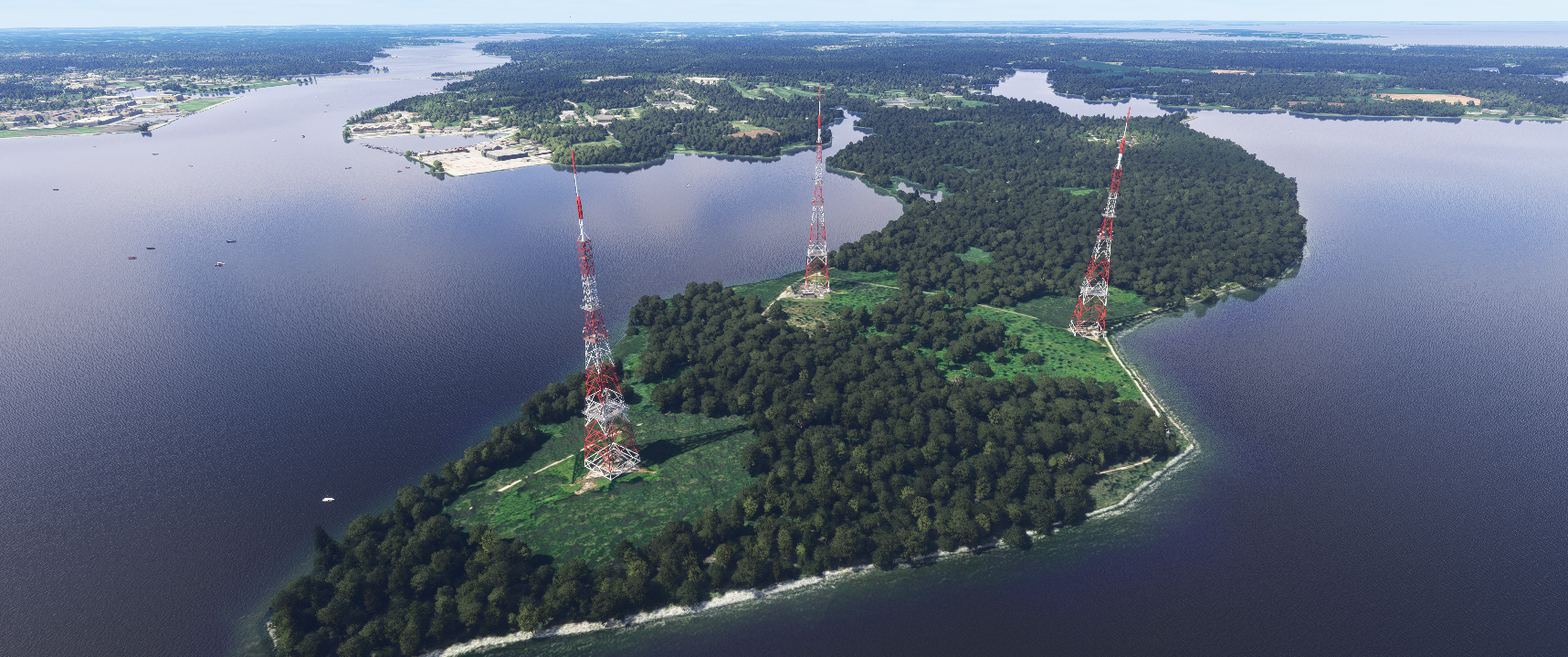
VLF Station 6, Maryland
Station 6 was located in Annapolis, MD. It consisted of one 370 metre and three 180 metre towers. The site was shut down in 1996 and the 370 metre tower was demolished in 1999.
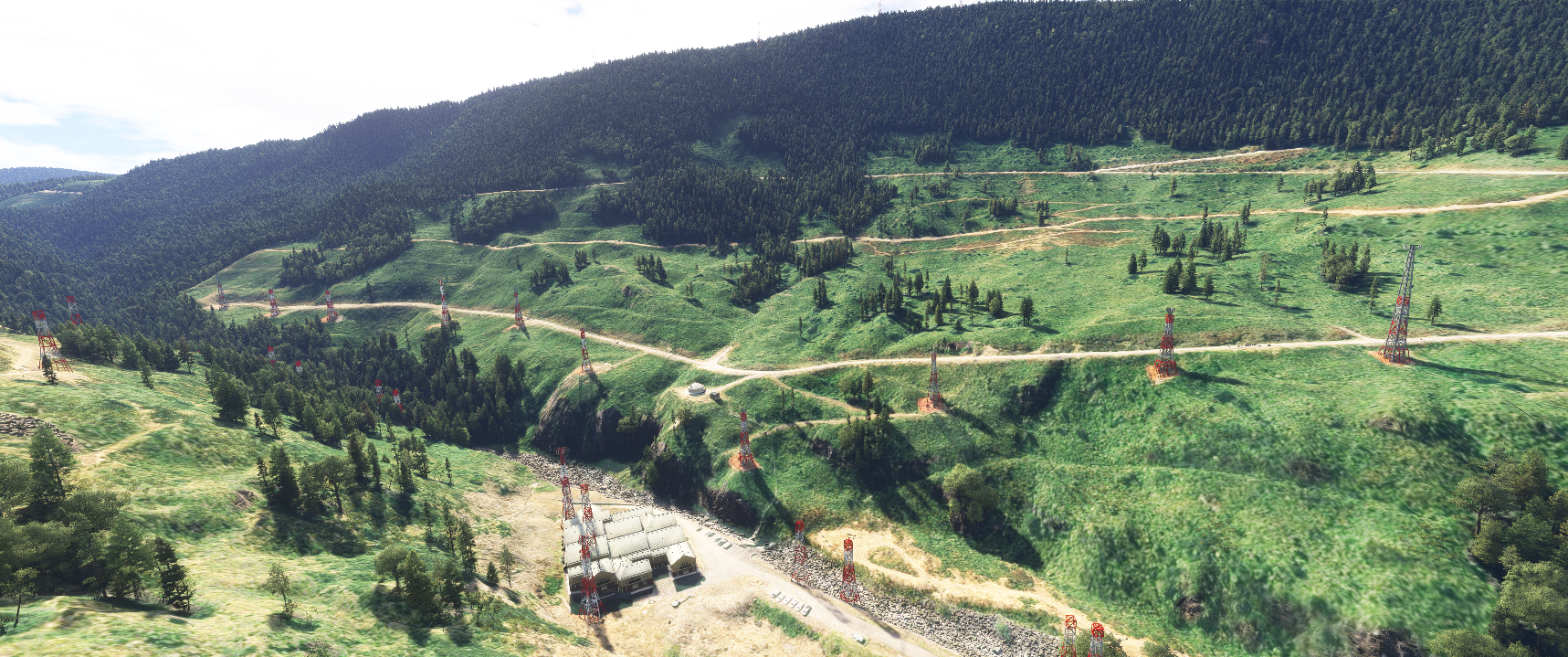
VLF Station 7, Washington
Station 7 is the Jim Creek Naval Radio Station located near Oso WA. The site was established in 1953. The antenna consists of ten catenary cables ranging from 1700 to 2650 metres in length suspended over the valley between Wheeler and Blue Mountains.
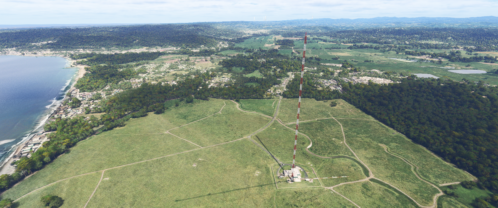
VLF Station 8, Puerto Rico
Station 8 is operated by the United States Navy. Its tower is 367 metres tall and is the tallest structure in Puerto Rico and the broader Caribbean.
-
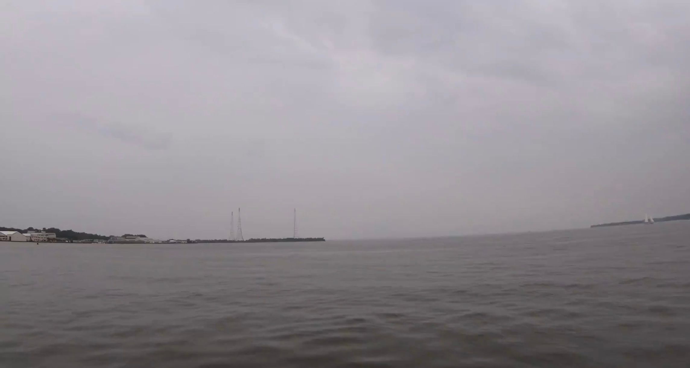 I had to take a screenshot from a video I took at USNA while visiting my son there. Across the water from the years, you can see the three remaining VLF towers. Sorry. It was a drizzly day.
 -
 M MarkS referenced this topic on